• Please join our new sister site dedicated to discussion of gold, silver, platinum, copper and palladium bar, coin, jewelry collecting/investing/storing/selling/buying. It would be greatly appreciated if you joined and help add a few new topics for new people to engage in.

    Bullion.Forum

Non-Chemical Gold cell

Gold Refining Forum

Help Support Gold Refining Forum:

This site may earn a commission from merchant affiliate links, including eBay, Amazon, and others.

glondor

Well-known member
Joined
Jun 13, 2010
Messages
1,539
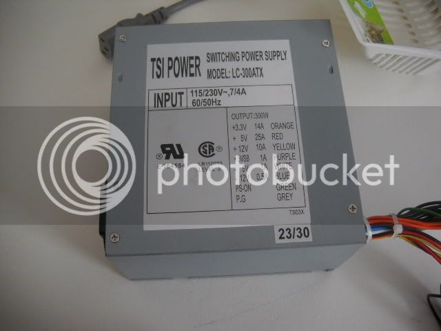
I am looking for your expert advice as I have a few choices to make and would as for help in making them. I am going to get a gold stripping cell going and I seem to have too much stuff to choose from. First I have 2 power supplies, neither one meets the recommended requirements as per hundreds of forum posts, but I hope either or both will do with one preferable to the other. The first is a typical PC power supply using the 12 volt 10 amp rail or the 3.3 volt 14 amp rail.

DSCN1697.jpg


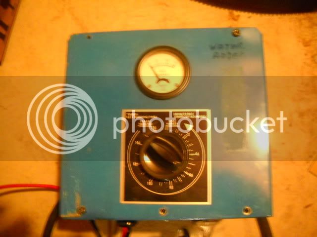
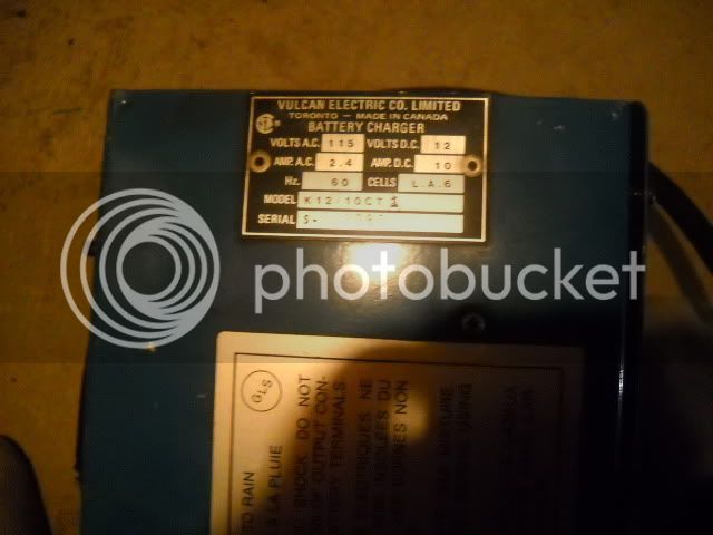
Or I have an industrial battery charger with a 12 volt 10 amp rating, This one has an amp meter and a timer.

DSCN1693.jpg

DSCN1695.jpg


Will either or neither of these work? Which would be better for a 1 liter cell.

Next, I have a choice for cathode, a small hatchet head or some lumps that I think are lead ( these are weights out of old phone handsets and bases, heavy like lead, but may be an alloy)

DSCN1696.jpg


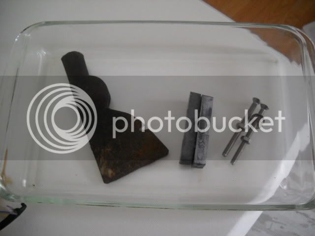
Will either work? Which would be better keeping in mind the lead slugs may be an alloy?
Thanks to Steve, (Props for the excellent videos) I have the copper mesh and I will use the pyrex dish in the photo. I have sulfuric and a whack of plated Jewelry I would like to process.
Any input would be much appreciated. Thanks.
 
For some excellant advice on anode materials go to the TUMBLER CELL thread and near the end read GSP posts. To my amazement there are very few metals including iron that will be attacked in concentrated Sulphuric.

http://www.goldrefiningforum.com/phpBB3/viewtopic.php?f=84&t=5810

Since I've never referenced a post before I'll be curious to learn if this worked.

I don't understand why you think neither of those supplies will work. I see either of them as being OK, but favor your battery charger. If current runs too high you might use Barren's suggestion of reducing the AC supply with a standard bulb dimmer or simply run less at a time. The dimmer approach might not work as well on a complex switching type computer supply.

With a silver cell you need more voltage control and that can be provided external to suppplies like you have.

FrugalEE
 
Thanks FrugalEE. Your link worked. I will try tonight with the axe and the battery charger. After I read your link. Cheers and thanks for your help.
 
1. battery charger is oK
2. keep proportions of Steve cell .... it is +/- critical
3. catode it is lead! (do not run lead/tin alloy) ....personaly I use old lead
pipes
4. Steve Cell it is perfect balanced.... Anode/catode/electrolyte/current/intensity!!!! ....keep in mind that !

My english it is limited....sorry!
 
nch, the metal at the positive side (anode) is what gets dissolved (oxidized), in a cell, the positive lead from external power source (usually red).

did you mean the cathode side was lead?
 
FrugalEE said:
For some excellant advice on anode materials go to the TUMBLER CELL thread and near the end read GSP posts. To my amazement there are very few metals including iron that will be attacked in concentrated Sulphuric.

http://www.goldrefiningforum.com/phpBB3/viewtopic.php?f=84&t=5810

Since I've never referenced a post before I'll be curious to learn if this worked.

I don't understand why you think neither of those supplies will work. I see either of them as being OK, but favor your battery charger. If current runs too high you might use Barren's suggestion of reducing the AC supply with a standard bulb dimmer or simply run less at a time. The dimmer approach might not work as well on a complex switching type computer supply.

With a silver cell you need more voltage control and that can be provided external to suppplies like you have.


FrugalEE

I wouldn't put the dimmer on the AC(line side) of the transformer I would put it on the DC (load side) of the transformer. You should also if capable of doing so have an amp meter and voltmeter to read your ouput and load on the DC side.
 
butcher said:
nch, the metal at the positive side (anode) is what gets dissolved (oxidized), in a cell, the positive lead from external power source (usually red).

did you mean the cathode side was lead?

This is whay I can't post ...I Make Many Mistakes...one eye to english
one eye to translation....and losing the Ideea :))

P.S I wish I can get gold from lead :p
 
nch said:
butcher said:
nch, the metal at the positive side (anode) is what gets dissolved (oxidized), in a cell, the positive lead from external power source (usually red).

did you mean the cathode side was lead?

This is whay I can't post ...I Make Many Mistakes...one eye to english
one eye to translation....and losing the Ideea :))

P.S I wish I can get gold from lead :p

I can understand the problem you are having. We can read between the lines and decipher make out what you are trying to say or ask so keep working at it. It will get easier for you as time goes by.
 
The secondary of a transformer is almost always the outer layer (winding) of a transformer,
if I wanted to lower the output voltage of a transformer, i could unwind some wire (measure secondary voltage) cutting it off here, or could tap it at this point and rewind wire back for original voltage.


a transformer usually has two windings, a primary coil and a secondary coil.
the number of turns on these coils determines voltages of these coils.
amperage will be determined by size of wire.
in a transformer watts in equals watts out.
the basic transformer can be used to step up or step down voltage, you can use either winding as primary depending what you wanted it to do.

say I have a imaginary transformer, 100 turns primary coil, and 10 turns secondary coil, (10:1 ratio), now if I put 100 volts to primary I would get 10 volts out, but if I turned this around and made what was the primary winding my secondary winding, and put 10 volts to (new)primary I would get 100 volts out my (new)secondary winding.

now back to watts in = watts out, say this is a 2 VA (watts) transformer, and 100 volts into primary, my amperage would be 2Watts/100volts=0.02 amps , and my secondary 10 volt would give 2 watts/10volts= 0.2 amps.
so we can see from OHM'S law, if we step down the voltage our amperage is higher , but if we step up the voltage our amperage is lower.

A simple car battery charger can be modified very easily to give any output of DC voltage ( lower than the normal 14.5 volts used for charging 12volt lead acid batterys, just by modifying the secondary winding of the transformer coil.

now lets take the above example transformer 100 turn primary 10 turn secondary, and cut half of the secondary winding off giving us a new 5 turn secondary winding, so now 100 volts in would give 5 volts out, and for this 2VA transformer our secondary current would give 2watts/5volts=0.4 amps .
 
butcher said:
The secondary of a transformer is almost always the outer layer (winding) of a transformer,
if I wanted to lower the output voltage of a transformer, i could unwind some wire (measure secondary voltage) cutting it off here, or could tap it at this point and rewind wire back for original voltage.


a transformer usually has two windings, a primary coil and a secondary coil.
the number of turns on these coils determines voltages of these coils.
amperage will be determined by size of wire.
in a transformer watts in equals watts out.
the basic transformer can be used to step up or step down voltage, you can use either winding as primary depending what you wanted it to do.

say I have a imaginary transformer, 100 turns primary coil, and 10 turns secondary coil, (10:1 ratio), now if I put 100 volts to primary I would get 10 volts out, but if I turned this around and made what was the primary winding my secondary winding, and put 10 volts to (new)primary I would get 100 volts out my (new)secondary winding.

now back to watts in = watts out, say this is a 2 VA (watts) transformer, and 100 volts into primary, my amperage would be 2Watts/100volts=0.02 amps , and my secondary 10 volt would give 2 watts/10volts= 0.2 amps.
so we can see from OHM'S law, if we step down the voltage our amperage is higher , but if we step up the voltage our amperage is lower.

A simple car battery charger can be modified very easily to give any output of DC voltage ( lower than the normal 14.5 volts used for charging 12volt lead acid batterys, just by modifying the secondary winding of the transformer coil.


I agree but not everyone is going to be comfortable doing this.
 
Barren wrote:
"I wouldn't put the dimmer on the AC(line side) of the transformer I would put it on the DC (load side) of the transformer."

We must be talking about different devices. A common 300 watt SCR or TRIAC dimmer available for a few dollars is what I had in mind and it is strictly an AC device and meant to work in 120 volt circuit at relatively low current levels. I still think that is a cheap and easy way to reduce voltage. Regulation isn't going to be very good, but should be OK for stripping.

Other thoughts:
Harbor Freight sells a nice little digital multimeter for $3 that compared favorably to my Fluke 8020A. It will even measure currrent, but only to 200 mA so you would need a shunt.

If I needed a low cost adjustable supply I would use a computer supply as a basis and add an external adjustable regulator. It should be pretty easy to find a power NPN transistor already mounted on a heat sink in some salvagable elelctronic device and that plus a low power potentiometer and a few other cheap parts are all you need.

FrugalEE
 
You can do it either way. If and when I set one up I will possibly do it on the DC side. I have a couple of systems I got from one of the members last year, I just haven't put them in use yet.
 
Adjusting on the secondary side will require more costly components.

The primary side of a 12V, 10A battery charger should be around 2.2A. The higher the amp rating the higher the cost.
 
FrugalEE said:
Barren wrote:
"I wouldn't put the dimmer on the AC(line side) of the transformer I would put it on the DC (load side) of the transformer."

We must be talking about different devices. A common 300 watt SCR or TRIAC dimmer available for a few dollars is what I had in mind and it is strictly an AC device and meant to work in 120 volt circuit at relatively low current levels. I still think that is a cheap and easy way to reduce voltage. Regulation isn't going to be very good, but should be OK for stripping.

Other thoughts:
Harbor Freight sells a nice little digital multimeter for $3 that compared favorably to my Fluke 8020A. It will even measure currrent, but only to 200 mA so you would need a shunt.

If I needed a low cost adjustable supply I would use a computer supply as a basis and add an external adjustable regulator. It should be pretty easy to find a power NPN transistor already mounted on a heat sink in some salvagable elelctronic device and that plus a low power potentiometer and a few other cheap parts are all you need.

FrugalEE
Rather than risk damaging my DVM. I use a low value resistor (depending on the current needed) and measure the voltage across the resistor to determine the current flowing through it. 1 AMP thru 1 OHM =1 Volt is a handy rule to remember. I've built many power supplies over the years, and I always add current limiting. It's always a handy feature when experimenting to prevent the Magic Blue Smoke from appearing. :mrgreen:
 
Irons, I too would much rather measure drop across a resistor or shunt to meter current. DVMs are pretty forgiving for over voltage, but not for over current. I've used a .1 ohm resistor quite a few times and they were easy for me to come by, but it's hard to find anything less so for higher currents you need to buy a shunt or make one out of something like iron or copper wire. Precision shunts require special alloys to be stable (Manganin), but I don't think refiners need precision.

Computer supplies:
I haven't dug into computer supplies and I'm wondering do they typically have any adjustment for voltage? It seems they would either need to hand select some parts (labor expense) or add a pot. It's likely that if there is a pot it will have limited range.

Any commercial supply will already be current limited so any add-on regulation can be pretty simply done with just an emitter follower arrangement.

FrugalEE
 
It is working beautifully. As it is minus 12 degrees in my shed I don't seem to have to worry about heat issues. An added bonus is that I found 6 items in the 2 kilo batch that were carat gold. 10 and 14 carat. About 35 or 40 grams worth. Thanks all for your help. I could not get the cell over 2.5 amps, no matter what I tried, however it stripped steadily. Everything is black, The tongs, the rinse water, and the cell.
On another note I have 6 kilos of fingers almost done in the A/P solution and 6.497 kilos of fiber chips almost done in a bucket of HCL. Both batches should be done tomorrow I hope. The pins will go into the cell as I don't have nitric and don't really have a place to do it. I will just stir them around till they are done.
Lots of filtering and washing then on to acid/clorox. I hope to see my first button by Feb.
 
FrugalEE said:
Irons, I too would much rather measure drop across a resistor or shunt to meter current. DVMs are pretty forgiving for over voltage, but not for over current. I've used a .1 ohm resistor quite a few times and they were easy for me to come by, but it's hard to find anything less so for higher currents you need to buy a shunt or make one out of something like iron or copper wire. Precision shunts require special alloys to be stable (Manganin), but I don't think refiners need precision.

Computer supplies:
I haven't dug into computer supplies and I'm wondering do they typically have any adjustment for voltage? It seems they would either need to hand select some parts (labor expense) or add a pot. It's likely that if there is a pot it will have limited range.

Any commercial supply will already be current limited so any add-on regulation can be pretty simply done with just an emitter follower arrangement.

FrugalEE

There are no adjustments inside the power supplies.
 

Latest posts

Back
Top