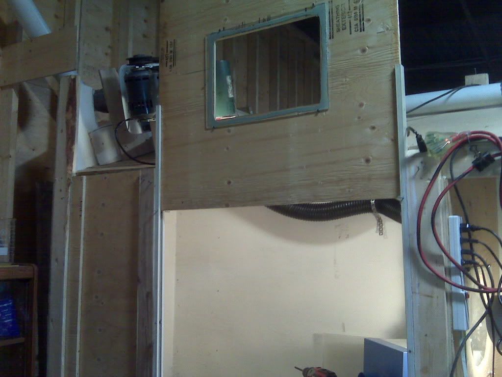
Fume hood venturi.

Gold Refining Forum

Help Support Gold Refining Forum:

This site may earn a commission from merchant affiliate links, including eBay, Amazon, and others.
goldenchild---

Yes, but I have changed my mind about what seems to be the optimum configuration several times since my last post! :oops:

It's a strange story---

I was looking at the 2" pipe with the 3" reducer going into the 3" "Y" fitting, and trying more things, with it attached to the shop vac today. Mainly trying to figure out where the suction comes from, and how the larger size "y" fitting actually works to enhance it.

I came up with three things.

First, if I inserted a 2" PVC pipe into the suction port of the 3" "Y" connector, the suction up the 2" pipe increased when I pushed it up into the air stream within the 3" fitting. I thought it seemed like it would do that, but wasn't sure if having the 2" pipe up in there wouldn't bog down the air flow, and just prevent any increased suction. But it worked.

Secondly, I got to wondering how that would affect more suction ports in a multi-port system. Maybe having that suction pipe sticking into the air stream would mess up the downstream suction ports?

Third, I was wondering how the additional volume of air coming up through the suction port would affect the air density/pressure in the main blow-flow line. That, as well as turbulance from the first suction pipe being right in the air stream, might just counter any additional suction possible from additional suction ports.

So to get back to your question, I was then thinking, with the test setup I'm working with, the best configuration would be the 2" ID PVC pipe for air entry from the blower, going into a 2" to 3" reducer which goes into a 3" "Y" fitting. Then for the suction, a 2" PVC pipe going into a reducer to the suction port of the 3" "Y", but with the stop flange inside that reducer ground off to allow the 2" pipe to pass through and penetrate the air flow area.

Penetrating the air flow puts the air stream all around the suction pipe opening, making more "cavitation" area, and creating more suction. Cutting the suction pipe, on the end which goes inside the air stream, at a 45 degree angle, would result in, when that angle is combined with the 45 degree angle of the "Y" fitting's suction port, making the 2" suction pipe end-cut to be at a 90 degree angle to the blower air flow, creating even more opportunity for "cavitation" suction. But the bottom of the 2" suction pipe air stream opening is blocked from the blower air flow, by the 2" pipe, itself. So adding a collar to it, to extend straight down the center of the air stream far enough to go past the turbulance caused by the entrance of the 2" pipe, would allow the cavitation effect to exist completely around the 2" pipe tip in there. This would require a 22 1/2 degree cut on both the 2"suction pipe and it's collar.

At this point, I was thinking that a single-stage, rather than a multi-port, configuration would probably be more efficient, because of eliminating the efficiency losses at each port, and turbulence, and so forth.


But---the major problem with all this is that the thing now resemples the drawing from Ammen's book, which jimdoc posted on the first page of this thread!

So, it's gone full circle! Oh no's!

Which figures, because why would he put it in his book, unless it was the optimum configuration. They must have already worked this all out.

So, why didn't Ammen's setup work for glondor? It seems to me it's probably because he used a 3" going into a 4". the cross sectional area of a 3" ID pipe is 7.07 sq. in., and the area of a 4" is 12.56 sq. in. That's less than double the area of the 3". Is it that it must be at least twice the cross area? Or did he have too many bend fittings, which would reduce the the flow as much as a smaller cross area? Or both?

Another interesting point about Ammen's configuration is that it is just the opposite of the one which I was setting up and testing, above. In Ammen's, the blower air comes in via the smaller pipe, and goes down the larger pipe. In the setup I was testing, the blower air feeds the larger diameter pipe fitting, and the suction is drawn out of the smaller pipe which is inserted into the larger diameter fitting. Does this make a difference? Does Ammen's design create cavitation around the outside of the smaller blower air feed pipe, instead of creating it on the inside of the smaller suction port pipe like the arrangement that I was testing? Apparently it does, because supposedly it works.

I don't have a cad program, and the only scanner is connected to my wife's computer, and it's late, so if you still want a diagram of the "Y" fitting configuration, I'll have to do it tomorrow.

As for me, I need to pick up another reducer, so I can test the suction with it stuck into the air stream, and with the 45 degree angle on the air stream end, and also with the extension collar.

It might turn out to be easier and less expensive in fittings costs, to just use a 3" 90 degree fitting, and drill a hole in the corner of it, and pass the 2" suction pipe into that and far enough up it and into the following ducting, to get past any turbulance from the 90. And the 2" air feed pipe from the blower would go through a reducer into the 90, on the other end from the one that the 2" suction port goes down. And that would make it look even more like Ammen's drawing in reverse.

Which brings up the question of, if the same 90 were used, but in reverse, with the blower fed through the 2" pipe going in through the corner of the 90, would the end of the 90 without the blower pipe going up it, then become the suction port, as in Ammen's diagram? I guess it would. And is one of these configurations more efficient than the other? I'm guessing they will be the same. Except that if you blow through the smaller pipe, into the 90, and suck through the other end of the 90, you then eliminate two reducer fittings, and their cost.

Whichever way the venturi design goes, I think it's going to be very important to remember to compensate for whatever bends are in the exhaust ducting system, probably by going to a larger size than the venturi fittings section, which in my test case would be going to 4" exhaust ducting out of the 3" venturi casing.

If a system starts with 3", 4", or larger, out of the blower, the cross sectional area calculations are going to be very important, also ( 2 pi r squared).

I think that the maximum suction flow for a venturi system is going to turn out to be around half the CFM of the blower air out of it's feed pipe to the venturi unit. But I think the whole thing, with twice the size of blower, and the larger ducting required, would still be less expensive than an acid proof blower, unless you have a really long ducting run.
 
Blower has to be before the "throat". Suction is created locally at the throat. Think of how this airbrush gun works.

airbrush-gun.jpg
 
yes and as in the air brush model the exit or exhaust is very close to the throat or venturi .
what is missing is the restriction 4metals spoke about at the y or t .
There should be no elbows or other restrictions after the venturi just straight exhaust .
hope this helps I used your picture to express my view of what should work, hope you don't mind goldenchild.Untitled-1.jpg
 
shyknee---

I like your idea with the piece of plexiglass. It looks easy to make, too.

But so far, I don't see any point in restricting the air input flow to less than the area of the air input duct. It causes a loss in system efficiency for no reason. It looks like it would work if the "Y" was about twice the diameter of the blower air input duct, but I don't know what the efficiency would be, compared to having the suction port pipe totally inside the air stream.

A suction can be created by extending the suction port up into the air stream of a larger diameter throat, rather than the traditional smaller throat of the original Venturi design, without restricting the main air flow of the input from the blower.

The traditional Venturi configuration had no suction port, and the smaller throat section had the purpose of creating a way to have a different air speed versus pressure, in the same pipe line, and thus make a measurement of both sections at the same time, proving the trade-off of less pressure when speed was greater. This is like Ohm's Law for the electrical circuit current versus voltage trade-off.

So it appears that the initial restriction is not necessary in an air suction system, because if higher air speed over the suction port is desired, you can just get a bigger blower---rather than restricting the one you have, which would reduce it's efficiency.

With the suction pipe completely inside the stream, the cavitation effect would be developed for the length of the circumference of the pipe, which would be 3.14 times longer than the edge of the plexiglass piece. So I think the pipe extension would create more suction than the plexi baffle.

If I can find a small scrap cooling fan from one of the computer video boards, I think it would make a good air flow indicator. It should work in reverse, and put out a DC voltage, when it is spun by an air flow, and that voltage can be read on a meter. This won't be calibrated to read CFM, but it will work to compare blower output with the suction flow, and show any increase in suction for various configurations of the Venturi.

I'm not sure if the readout would be linear or not, that is, if twice the voltage would indicate twice the CFM, but putting one over both outputs of a "Y" connector would give a reading for half of the blower output, then measuring the blower output directly will give the reading for twice the air flow, and that should give an idea of how proportional the voltage output is to the different air flows.

I was up late last night making my previous post, so now I need to get some breakfast and stuff, then see if I can do the fan tests.
 
P.S. If anyone is wondering if the exhaust ducting resistance is all that important to consider, just think of it this way---everything always takes "the path of least resistance."

So if the exhaust presents even slightly more back-pressure than the suction path, it will blow air out the suction port.

And as the exhaust resistance approaches that of the suction port, the suction starts to reduce.

For air suction configurations, the Venturi Effect which applies, is the larger diameter outflow duct, not the smaller diameter throat.
 
eethr
But so far, I don't see any point in restricting the air input flow to less than the area of the air input duct. It causes a loss in system efficiency for no reason. It looks like it would work if the "Y" was about twice the diameter of the blower air input duct, but I don't know what the efficiency would be, compared to having the suction port pipe totally inside the air stream.

A suction can be created by extending the suction port up into the air stream of a larger diameter throat, rather than the traditional smaller throat of the original Venturi design, without restricting the main air flow of the input from the blower.


Yes, I agree totally.
I just can not test it at this time
 
So what I think you guys are saying is something like a 3 inch system with a 3 inch to 1.5 inch "T" for the throat? And a 1.5 inch pipe slighty extened into the blowers air flow path? Or just 3 inches all around? You would then have to test efficiency with how far up into the airflows path the pipe would go.

BRFC.jpg


P.S.
I orginally tried the 3 to 1.5 inch T without a pipe in the airflow path and can tell you that air was blow into the hood.
 
goldenchild said:
So what I think you guys are saying is something like a 3 inch system with a 3 inch to 1.5 inch "T" for the throat? And a 1.5 inch pipe slighty extened into the blowers air flow path? Or just 3 inches all around? You would then have to test efficiency with how far up into the airflows path the pipe would go.


P.S.
I orginally tried the 3 to 1.5 inch T without a pipe in the airflow path and can tell you that air was blow into the hood.

It might work better if you have a 90 on the smaller pipe inside the tee faceing downstream.
 
Barren Realms 007 said:
It might work better if you have a 90 on the smaller pipe inside the tee faceing downstream.


Barren---

I think that is true.

It seems that, besides the suction port style, the most important thing is that the output duct's cross sectional area needs to accomodate the volumes of the blower air flow plus the added air from the suction port. Apparently this needs to be true from the beginning of the suction port, onward.

I think that a suction port which is smaller than required, will only restrict the suction, however.
 
Here is a diagram of what I think will work best for a "Y" fitting suction Venturi, from what I have tested so far. Note that I haven't tested the 45 degree cut in the protruding suction port, nor the collar.

It's a little sloppy, because I just used a draw program instead of a CAD.


suctionventuri7.jpg


It might turn out that using the large 90 degree fitting for the Venturi casing is more efficient. Or reversing the blower input and the suction pipe, as in Ammen's diagram, might be even better.

Also, it might be better to make the Venturi section longer, to accomodate making the suction collar longer in order to put the cavitation area at the end of it further away from the turbulence caused by inflow air hitting the back of the suction pipe.

Note that the larger size of the exhaust ducting is not to create suction, but to prevent back pressure from air friction against the inside of the ducting run plus any turns in it. The "Y" fitting, acting as the Venturi casing, is already larger, to accomodate both the blower inflow air and the additional air entering the system from the hood, through the suction port. By having enough cross sectional area to handle both air flows inside the Venturi section, it allows the cavitation to form at the end of the suction collar and create the suction effect without having back pressure cancel it out.
 
shyknee---

I only now noticed that what you drew in your venturi drawing is of the style which is in Ammen's book, shown on the first page of this thread.

I like the use of the "Y" better than the large 90 degree fitting that I thought of for his method. Your "Y" arrangement has 45 degrees less drag, and could simply go into the hood at 45 degrees.

It looks like it only requires the "Y" fitting and an end cap for parts, too. Plus making a hole in the end cap for the blower pipe. In both the large 90, and your "Y" fitting configurations, some kind of additional support for the blower pipe will be most likely be needed, but that could probably be easily provided by extending the blower mounting platform and strapping the "Y" to it, or to a vertical backing added to the platform.

It should be remembered that with multiple hood ducts, the total suction will be split among them. And the ones toward the far end of the suction ducting run might not draw very much if the hood down-pipes are all the same size.
 
I gave up on venturi for now. I priced an acid resistant blower and the price was 4400 plus taxes. Out of the picture for me. I will use a sacrificial system for now with the blower in the stream. Main blower at top left on top. Smaller blower inside hood for lower level air flow. Ducted to main blower intake. Few minor kinks, works well until I come up with something better. No fumes in the work-space with full on nitric boil. Using an ice cream tub and marbles as a bit of a condensor. I will work a new system in the empty right side of the hood with a proper scrubber and proper blower.
IMG00546.jpg

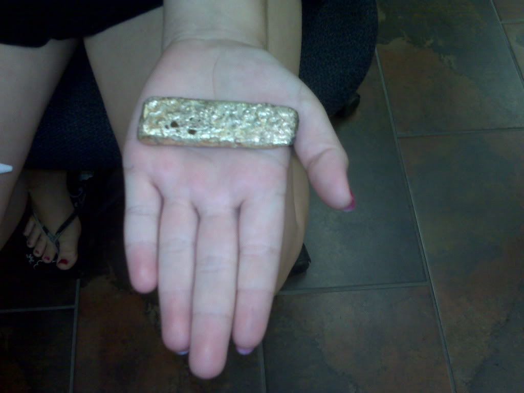
Here is my daughter holding our first real gold bar.
IMG00527.jpg
 
glondor said:
...Few minor kinks, works well until I come up with something better.


I know what you mean. I used a shop vac, and put three coats of teflon spary-can paint, from a hardware store, on the empeller. I used it about a dozen times, took it apart, and couldn't tell any difference. It's the same one I am using to experiment on the venturi configurations with.

I might even just end up using it in the regular way, too. After all, it has both the inner bag filter, and the cylindrical filter cartridge. (I got it at Walmart.)

I tried using it to suck the air from the hood, through standing water, by putting a 4" PVC from the hood into a plastic garbage can with water in it. But all the ways I tried it, the air flow was very poor.

I did discover, however, that just directing the hood pipe downward at the water, and about an inch or so off the surface, built up a large amount a acidity in the water after just a couple of uses that way. It appears that most of the air was actually contacting the water surface, and the water was capturing lots of the fumes right there. I'll have to tape some litmus paper in the end of the exhaust duct, when I get my new fume hood built, and see about how much of a difference it makes compared to litmus taped directly inside the end of the hood outlet for the same amount of time (like 60 seconds). It might work good enough for occasional refining.


P.S. Nice bar!
 
Well, I tried the 45 degree angle on the 2" suction pipe, extending it up into air stream of the 3" "Y" fitting. It did increase the suction. I haven't dug up a small video card fan to make meter measurements yet, but I tried a piece of notebook paper, holding it away from the pipe, and slowly bringing it closer. It slaps it up against the 2" pipe opening when it comes within an inch away from it.

If I have time, I'll try it after adding the collar piece, tomorrow.
 
glondor said:
I gave up on venturi for now. I priced an acid resistant blower and the price was 4400 plus taxes. Out of the picture for me. I will use a sacrificial system for now with the blower in the stream. Main blower at top left on top. Smaller blower inside hood for lower level air flow.

For what its worth. You should coat those blowers with the stuff I pictured above. My blower is holding up extremely well. Even after some aggresive AR reactions. I am very surprised.

Just take the blowers apart and put it on nice and thick on all pieces. It dries fast too. Using it like you have now wont hold up for long at all. Especially when the AR hits. Keep in mind they also sell plasic fan wheels. Good luck.
 
Well, I did add the collar piece the other day, but had varying results.

Because I was using the 3" suction port pipe inside the 4" "Y" suction port, there was a void area at the base of the sustion pipe, inside the "Y." I had simply stuffed some thin filler paper around the 3", in order to hold it in and make it air tight around it. But the filler paper only went as far as the wide part of the end of the "Y" fitting which is supposed to have a 4" PVC stuck into it. This created a cavity or void, below where the intake of the suction 3" with the collar was.

If the pipe was tilted so that the collar intake was forward, no suction resulted. But if I tilted it back as far as it would go, it sucked better than just the 45 degree cut.

My next thought was to extend the collar 8" or so into an added 4" PVC section, so as to get the intake out of the turbulence area of that void/cavity. But there is no way to glue an 8" collar on, and then be able to insert it into the "Y" fitting.

So, the best shot at that kind of extension into the smooth air flow area is to go with the Ammen design, and have the blower enter the "Y" with an extended 3" and go past the suction port of the "Y" and into the added section of 4" PVC. This would require no bends in the 3", and then the suction port can remain the regular 4" of the "Y" fitting. So that's my next try.
 
Here is the Ammen type suction venturi. I tried it today, and it seems to have about twice the suction force as the best of the other type which I tested, above.

But this version has a full 3" suction port. It will suck a piece of notebook paper from 2", instead of the 1" of the previous versions. However, from a 3" opening on the hood end, that means over twice the cross sectional area as the previous suction port of only 2" diameter PVC pipe, so it probably means around four times the overall suction volume.

But it still feels like less than half of the shop vac's direct suction power.

It is much simpler to build, and with fewer fittings, it costs less, too.

This is what it looks like---

suctionventuriammentype.jpg


It will suck out the flame of a Bic lighter at 1", which is pitifully weak. However, this shop vac which I'm using for testing is only 5.5 Amps, and that's why the "blower input" PVC pipe is only 2" diameter. Actually, the hose for this vac is only 1 1/4" inside diameter, but the vac port is 2".

A larger, more efficient blower would probably provide plenty of suction for a fume hood adequate for home refining. There is one listed for only $46.49 ($43.50 less than this shop vac I'm testing with cost) at Lowe's, and, because of the vac's 1 1/4" ID hose, I assume that this blower has way more air volume.


Last edit: Added word "vac" after "shop," and changed "vac post" to vac port," in paragraph 6.
 

Latest posts

Back
Top